
If you’ve heard of USB 3.2 Gen 1 headers and other PC-building languages, then you have an idea of the different headers involved. Still, it can be daunting to understand what the USB header is and how they function.
What we do know is that a USB 3.0 is different from a USB 3.2 Gen 1 header and others designed for different versions of USB ports on the PC case.
In this article, you will learn all that you need to know about headers, with an emphasis on 3.2 Gen 1 header.
Contents
An Introduction to the USB 3.2 Gen Headers
USB headers are essentially the connectors that help ensure that all USB devices are connected and functioning correctly. Depending on the type of USB header, you will most often find them positioned on the right side or bottom of the circuit board.
If you are trying to locate the USB headers, all you need to do is look for labels that say either F USB, J USB, FPANEL USB, F USB2, or something similar on your motherboard, and there you have it; those are your USB headers.
However, if you find that difficult to do, you can refer to your motherboard’s manual and follow the specified steps and directives designed to help you locate the USB headers.
Overall, these are the types of USB headers that are available on most motherboards, and the headers differ in terms of the number of pins and their configuration. For your own benefit, it is important to understand them. That’s why we will be discussing all of them in further sections.
Major Differences Between USB 3.2 Gen 1 Headers and Other USB Headers
The major differences between USB 3.2 Gen 1 headers and other USB headers come due to the different number of pins in the headers and their arrangements. Moreover, compatibility and scope of usage also count as major differences between the headers.
Have you designed and built a custom PC from scratch before? If you have, then you know it’s essential to learn what USB header types your motherboard supports.
The headers also differ from one another when it comes to the number of pins and ports they can support. It is true that most USB headers can use two USB ports, but some only support one.
In addition, the header types often correspond exactly to the USB generations. What this means is that the USB header will only support the type of USB generation you have. For instance, the USB 3.0 can’t be placed in the USB 2.0 header because of its size incompatibility.
On that note, USB headers are generally classified into four types or generations. We will shed more light on each of them in this section.
– USB 2.0 Header
You can confirm that you have a USB 2.0 header in a simple way. You will see that the label on the motherboard mentions ‘USB 2.0’. Also, this is one of the most common headers around, and it is located in the bottom part of most motherboards.
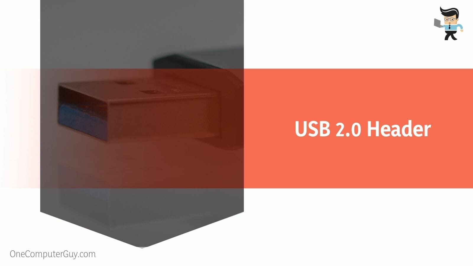
In USB 2.0 headers, there are nine pins in a 5×2 arrangement, which implies that there are exactly five pins on each row, but one pin is missing on the second row. Don’t worry; it is that way to ensure proper alignment.
– USB 3.0 Header
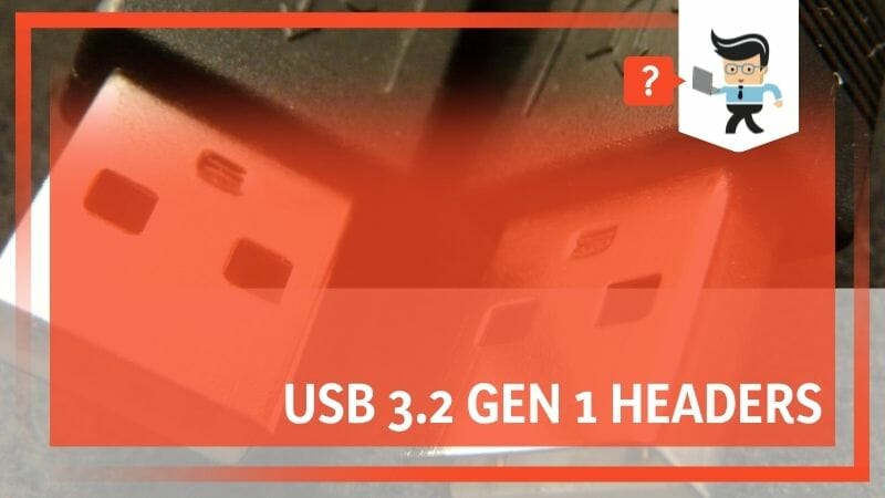
Don’t get it mixed up here. But a USB 3.0 header is also known as USB 3.1 Gen 1 and USB 3.2 Gen 1 header. A USB 3.0 header comes with 19 pins arranged in a 2 x 10 array.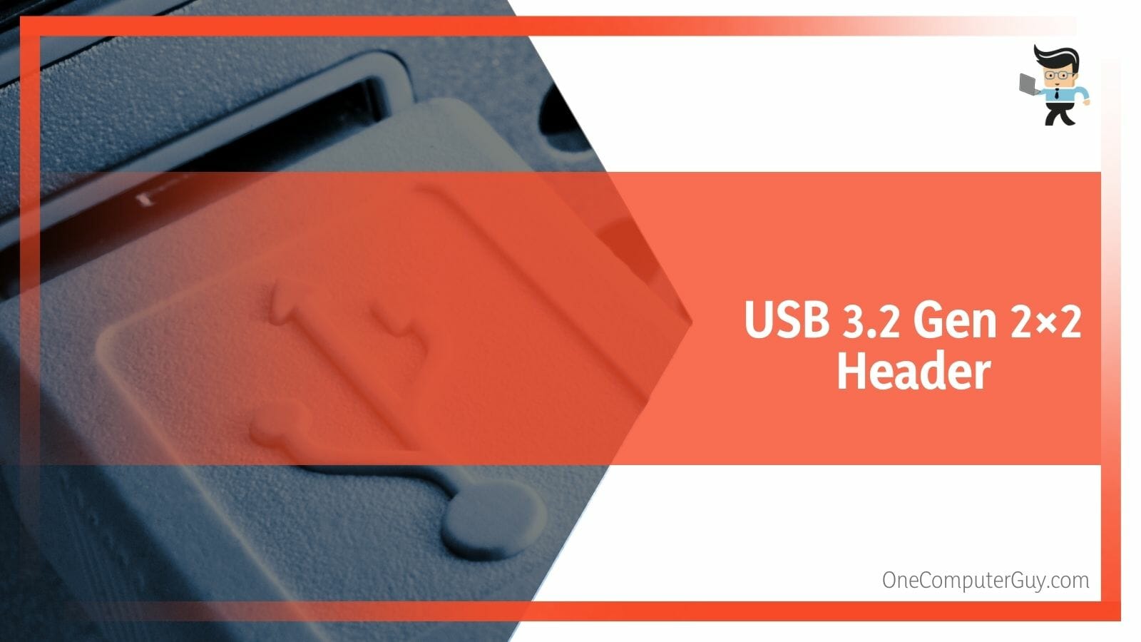
Basically, the name that you see for this header on any motherboard spec sheet depends on when the motherboard was manufactured. For example, the latest motherboards label this header as USB 3.2 Gen 1 header, while the older motherboards may have other names.
As the USB standard changes the nomenclature, so do the motherboard manufacturers, but they are all essentially the same. If you have a PC case with USB 3.0 / 3.1 Gen 1 / 3.2 Gen 2 ports, you will find that they all come with similar cables.
– USB 3.1 or 3.2 Gen 2 Header
Like the USB 3.0 header examined above, a USB 3.1 or 3.2 Gen2 port can be found either on the right side or on the bottom of the motherboard, depending on the configuration of your motherboard.
However, it has a simpler form factor. While the two previous generations had pin arrangement, the USB 3.1 does not have such a configuration. Instead, these headers adopt a unique metal casing with no pins sticking out.
– USB 3.2 Gen 2×2 Header
The USB 3.2 Gen 2×2 header is basically the advanced form of the USB 3.2 Gen 2 header. Keep in mind, however, that they’re only located on the right side of the motherboard, as there is no other spot for them.
Aside from that, the channel is the one and the only thing that differentiates these two headers from one another. While the USB 3.2 Gen 2×2 header can support two channels simultaneously, the USB 3.0, 3.1, and 3.2 headers can only support a single channel at a time.
It’s interesting to note that the USB 3.2 Gen 2×2 headers are also known as the USB Type-E header, and their appearance is almost exactly the same as that of the USB Type-A ports, although they are rare to come by as they might only be available on modern and costly motherboards.
– F_USB vs. J_USB
Many users ask what is the difference between F_USB and J_USB? Well, many motherboard makers designate front panel USB ports with labels that begin with F_USB1 or F_USB2, respectively. Therefore, the word “Front” is frequently denoted by the letter “F” in the USB headers.
But note that this may not be applicable to all motherboard models. One of the reasons for this is that a lot of manufacturers use a variety of letters to denote the location of USB ports on their products. On MSI motherboards, for instance, you may come across variations such as J_USB1, J_USB2, or others like them.
Before recent times, older PCs only used J_USB headers, with J denoting ‘Jumper,’ and they only supported half-duplex communication. Unfortunately, this created a deadlock, which often led to malfunctioning USB devices.
Much later and recently, several manufacturers have switched to USBs that supported full-duplex mode and named them F_USB. But currently, you can find J_USB on MSI motherboards supporting full-duplex, and the letter ‘J’ now stands for ‘Jack.’
Ultimately, the only major difference that exists between F_USB and J_USB lies in their indications as assigned by different manufacturers. That means you might find other letters which could very well mean the same thing and do the same work.
How to Locate the USB 3.2 Gen 1 Header?
To locate USB 3.2 Gen 1 Headers, check at the bottom or the right edge of your motherboard. Still, there’s no harm in getting to your headers faster by looking at the motherboard directly. You can locate your USB headers in two ways – physical Inspection and via the manual.
– Physical Inspection
Physically inspecting your motherboard will easily lead you to the location of your USB headers.
Besides, the headers are often labeled and may also indicate what version they belong to.
– Through the Manual
Getting a new motherboard means that you gain access to where your USB header is located. Use it to check your motherboard’s layout to find possible USB headers.
How to Connect USB Ports to the USB 3.2 Gen 1 Header?
You can connect USB ports to the USB 3.2 Header by identifying your pins. The most common type of pin is the VCC, and you can connect to it by checking the color of the wire. The second one is the DATA pin, found next to the VCC.
After becoming familiar with the various types of USB headers, the next step is to get knowledge of the USB cable that is located internally. Basically, these are the extension cables with which you can connect the USB ports to the USB headers.
At the moment, there are two types of internal USB cables available – one that has a USB header jack and one that has individual wires for each pin on the USB connector.
Although they both work in the same way, the connecting procedure for the latter one is a bit technical. As a result, if the connection isn’t secure, you might encounter some errors, such as ‘USB Device Over Current Status Detected.’
– Know Your Pins
Before going further, it’s essential to know what each of the connectors of the internal USB cable stands for, where to place them, and most importantly, why they are used:
- VCC Pin: Also known as Voltage Common Collector, its major function is to carry a +5 V signal that allows it to supply power to the USB ports. If you want to locate this pin, carefully check through the pin’s label, which should say “VCC,” or identify the red-colored wire.
- DATA- Pin: This pin is colored white and lies next to the VCC pin. Basically, the DATA- pin is responsible for passing on downstream data connections.
- DATA+ Pin: Like DATA-, the DATA+ pin passes the upstream data connections and provides proper communication between your computer and USB devices. You will find it next to the DATA- pin with green wiring.
- GND Pin: Also known as the Ground pin, it is helpful for the reduction of electromagnetic interference. Additionally, it transmits the voltage carried by the VCC pin to the motherboard. Because of this, the USB device does not send any more current to the motherboard, and vice versa; as a result, the risk of short-circuiting is eliminated.
With a good idea of the types of pins and their locations, you can now learn how to connect both types of internal USB cables to the USB headers.
– Connecting the Internal USB Cable Jack
If you’re using a USB 3.0 or above, the possibility of finding a jack instead of individual wires is high. That makes it relatively easy to connect it to the USB header without a comprehensive knowledge of the pins and their configuration.
Additionally, some of today’s USB 2.0 internal cables also include a jack, making the connection even easier for tech novices. That said, we’ll demonstrate how to attach the USB header jacks on the motherboard to the USB headers on the inside of the device:
- Open the PC case with a screwdriver or simply by pressing the dedicated button, whichever is applicable.
- Next, take the front USB panel and ensure a proper connection. You can do that by inserting the connector into the port and tightening the connection by pressing both ends.
- Now place the USB panel in its dedicated slot on the PC case.
- Navigate to your motherboard to locate the USB header via the lakes of the ports. The location is normally to the bottom or right side, depending on the type.
- Now, insert the internal USB cable jack or the female cord into the USB header, ensuring correct pin alignment.
- Lastly, close the case and turn on your PC. Connect a USB device to see if everything works fine.
Note that some USB panels also come with a separate audio port cable. It has a different pin configuration and will not fit in the USB header. Instead, insert it into its dedicated motherboard port labeled F_AUDIO, JAUD1, etc.
– Connecting Individual USB Port Wires
Follow the procedure below to have a good idea of how you can connect the individual USB port wires to the USB headers:
- Use a tool to carefully open the PC case and ensure proper connection on the USB panel.
- Insert the two VCC wires on the first pin from the left of your USB header.
- The third step is connecting the DATA- wires adjacent to the VCC pins.
- Go ahead and insert the DATA+ wires next to the DATA-.
- Next, place your GND wired in the fourth pin, leaving the last one untouched.
- Replace the PC case, and turn on your PC.
- Lastly, connect any USB device like your mouse, flash drive, or keyboard to check whether they work or not.
– With Other USB Headers
Generally, a good number of motherboards have a maximum of two or three USB headers. However, if you plan on embedding another USB header, it’s impossible to do so.
Still, if you have a USB 2.0 adapter that supports a single USB device, you can join two such cables into one. This gives you a chance to use two different USB devices using a single USB header.
Follow these steps:
- Firstly, carefully take out the pins from one of the internal USB cable jacks. A flat tool or a pair of tweezers will do just fine.
- Next, gently insert each pin (VCC, DATA-, DATA-, and GND) into the empty slots on the other cable jack. As you do so, make sure that each one is correctly aligned on their respective positions based on the colors.
- Finally, insert the female connector into the USB header, enabling you to use two different USB devices concurrently.
Keep in mind that a USB hub will allow you to connect even more USB devices. The device works by utilizing a single existing USB port on your computer and transforming it into multiple ports.
Without adding extra USB headers, you can plug USB expansion cards straight into the motherboard’s PCIe slot.
FAQs
1. How Many USB Ports Will a USB Header Support?
USB headers can generally support up to 2 USB ports per header. However, that depends on the type of header it is. Basically, the number of pins in the header and their arrangement will determine how many ports a header can support.
2. Are USB 3.0 and 3.2 Headers Essentially the Same?
For the most part, yes, the USB 2.0 and USB 3.2 Gen 1 or USB 3.0 headers are the same including appearances and a similar pin-based design. However, USB 3.2 Gen 2 headers do not have visible pins but share similarities to USB Type-A in appearance.
Conclusion
Now you have a clear idea about USB 3.2 gen 1 header and a whole lot more about beavers in general.
Here’s a recap of the key points in the article:
- USB headers are prominent parts of a motherboard, and they ensure USB devices are correctly connected.
- There are four major headers, including the USB 3.1 Gen 1, USB 2.0 headers, and others.
- Pins are vital parts you must use to connect USB ports to the proper headers on your motherboard.
- You can locate headers in two ways, physically and via a manual provided by a manufacturer.
There you go! These are the essential things you need to know about USB 3.2 Gen 1 headers.


